One of the things I’ve been promising myself to do with my printers for a while is to get them properly lit. My workspace is in the back corner of the garage, and I spend a huge amount of time working under a small tasklamp.
Gogo gadget LED Strip!
I ordered a 5m roll of Warm White LEDs from Aliexpress (these ones). My initial thought was to connect them directly to the PSU, and just have them on whilst the printer was. I then realised the MKS SBase board I’m using has spare GPIO pins, so I decided to make it complicated and have them controllable using GCode. Whilst I was at it I decided to wire the hotend fan so it was possible to control that too.
All this snazzyness is enabled by one of these:
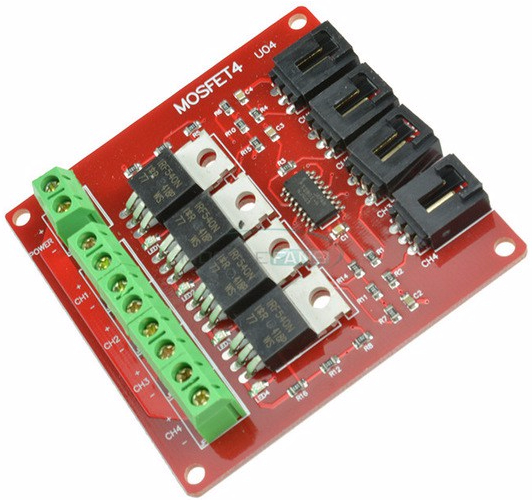
This is an ‘Arduino’ 4 way Mosfet board. They’re also available in 1 way.
How does it work?
The idea behind these boards is to take the low power output from the processor, and use the mosfet to drive high loads. The IRF 540Ns used on the board I got are rated (assuming they’re legit) to drive 30A, but bear in mind thats with a big ass heatsink. In free air I’d not run them more than maybe 1A. If you want to run bigger loads either grab one of the highload ones designed for beds, or som heatsinks for these parts (bear in mind the tabs need isolating from the heatsink.
When you’re selecting one I’d suggest you keep an eye out for one that uses an optoisolator (the small surface mount chip in the pic above). In theory you can drive the gate of a mosfet directly from the GPIO pins, but most of the boards I found use IRF540N mosfets, which aren’t really rated for logic level inputs. As far as I can make out from the wiring the optoisolators is used to drive the gate with the input voltage, rather than signal.
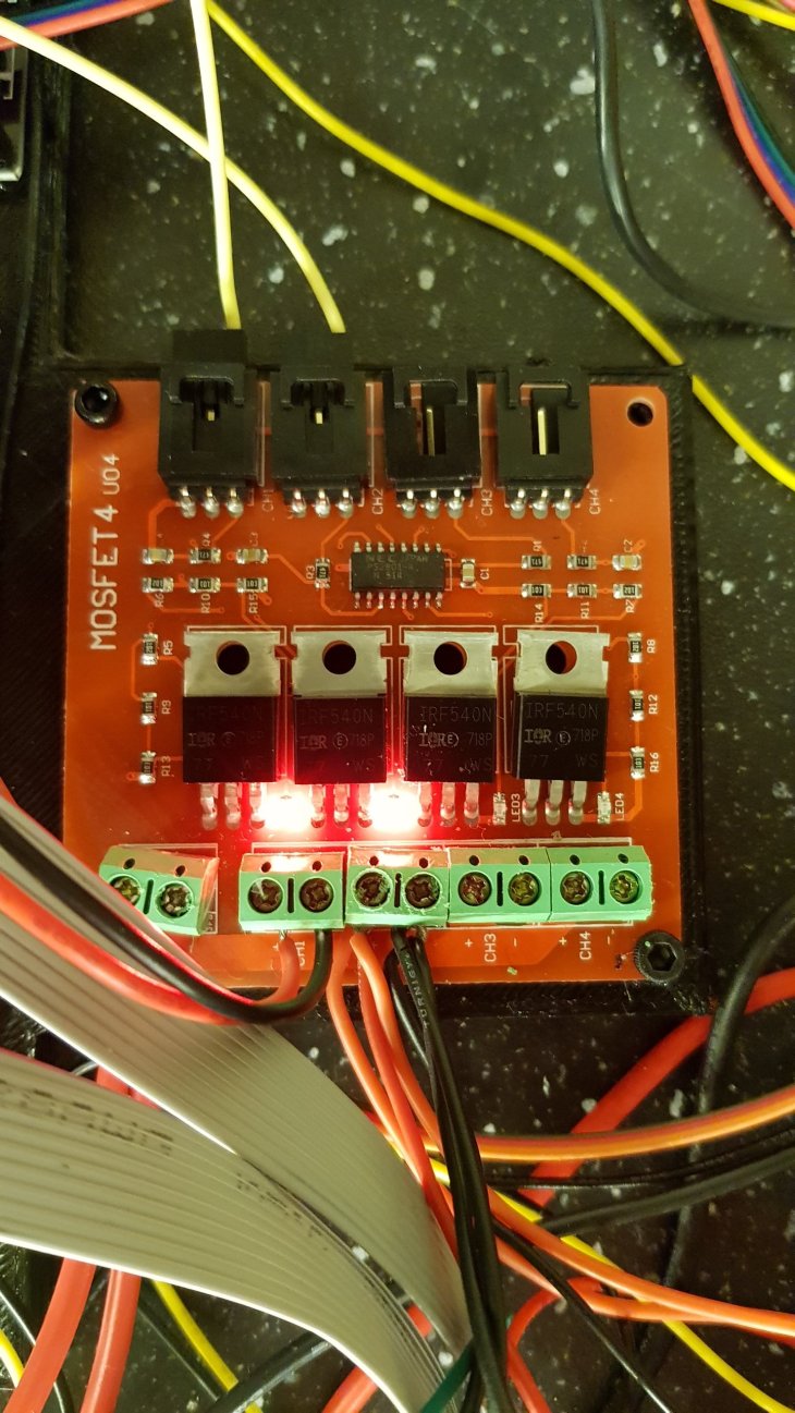
Wiring it up.
Wiring is pretty straightforward. Run a cable from a spare signal pin on your board to a one of the signal pins on the board (ignore the G/V pins on the input side, they’re not needed). Wire the +/- supply to your PSU and the devices you want to control to the outputs:
Configuration
Like most things smoothie related, configuration is pretty straightforward. This is the relevant config section (including a custom menu option for lights on/off:
#switches - Using J8 on MKS SBase GND P1.22 P1.23 P2.12 P2.11 P4.28
#hotend fan on 1.22 - temp controlled
switch.hotfan.enable true # enable
switch.hotfan.output_type digital #hotend fan should always run max
switch.hotfan.output_pin 1.22 # pin that controls the fan
temperatureswitch.hotend.enable true # enable this module
temperatureswitch.hotend.switch hotfan # select which MOSFET to use, must match a switch configuration (fan2 below)
temperatureswitch.hotend.designator T # first character of the temperature control designator to use as the temperature sensor to monitor
temperatureswitch.hotend.threshold_temp 60.0 # temperature to turn on (if rising) or off the switch
temperatureswitch.hotend.heatup_poll 15 # poll heatup at 15 sec intervals
temperatureswitch.hotend.cooldown_poll 60 # poll cooldown at 60 sec intervals

#lights on P1.23
switch.lights.enable true
switch.lights.output_type digital #lights on or off
switch.lights.output_pin 1.23
switch.lights.input_on_command M10 #CNC Specific vacuum code for no conflicts
switch.lights.input_off_command M11 #CNC Specific vacuum off
custom_menu.lights_on.enable true #
custom_menu.lights_on.name LightsOn #
custom_menu.lights_on.command M10
custom_menu.lights_off.enable true #
custom_menu.lights_off.name LightsOff #
custom_menu.lights_off.command M11
Update: Someone on facebook rightly pointed out that if you’re only controlling one thing, you can use the second extruder heater output to do so.

Hi Jebk,
Thanks for this write up.
I have an MKS base 1.5 board, so you think it would work on that?
LikeLike
No, or at least not exactly. The principle will work the same, but you’d need to configure marlin differently to smoothieware. I’m also not sure how many spare pins there are on that board
LikeLike